Stator Insulating Materials: The Importance of Semi-Conductive Materials and Their Application
A Review of Insulating Materials
Large rotating machines contain many different types of insulating materials, providing specific protection to maintain efficiency and prevent damage during normal operation, upset conditions, and idle states.
One type of specifically formulated insulation, semi-conductive insulation, serves a structural purpose, but most importantly, corona / partial discharge protection.
Insulation Degradation
The life of insulating components is determined by the severity of thermal, mechanical, electrical, and environmental stresses that the insulation is exposed to over time.
The integrity of insulating components in large rotating machines can be altered by exposure to many factors that are not present in a perfect world:
» High Temperatures
» Vibration
» Thermal Cycling
» Electrical Stress
» Mechanical Stress
» Moisture
» Chemical Exposure
» Contamination
Each of these factors can lead to or increase the severity of corona / partial discharge. Partial discharge produces ozone, salts, and carbon deposits.
The damaging cycle of these chemicals contributes to insulation degradation, which increases partial discharge activity — further reducing the insulation components’ integrity, eventually leading to dielectric failure.
Corona / Partial Discharge
Corona / partial discharge in rotating equipment is a condition created by a strong electric field ionizing gas molecules (e.g., Air). Partial discharge may occur anywhere a gas-filled void or gap is exposed to high electric fields.
Most stators rated at 4kV or higher require special materials to protect insulating components from the damaging effects of partial discharge.
Partial discharge can degrade insulating components over time but usually does not cause immediate failure. Damage caused by partial discharge is permanent. Identifying where partial discharge is occurring is critical, such that repairs can be made before extensive damage is done.
Corona / partial discharge degradation can be found in four areas:
» End Windings
» Internal To Ground-Wall Insulation
» Slot Discharge
» Surface Discharge
End Windings
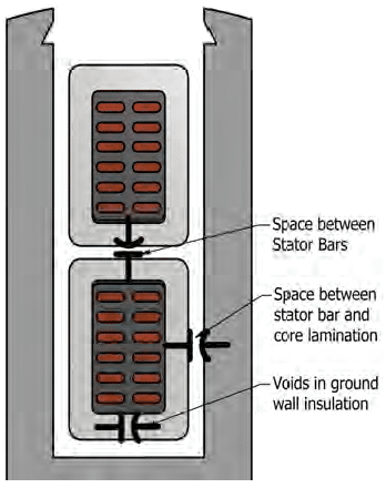
Partial discharge can occur in the end windings of the stator bars. Moisture/humidity, contamination, and insufficient spacing between stator bars are examples of contributing factors leading to partial discharge in the end windings.
Internal To Ground-Wall Insulation
Internal partial discharge is due to voids between stator bar conductors and the ground-wall insulation and voids in the ground-wall insulation. These conditions are created during the manufacture of the stator bars. Over time, internal partial discharge increases the size of voids and will eventually lead to dielectric failure.
Slot Discharge
Slot discharge occurs in the space between the stator bar and the stator core laminations. This type of discharge can be caused by loose stator bars, insufficient semi-conductive coating on the slot portion of the stator bar, and insufficient discharge path from the stator bar semi-conductive coating to the stator core laminations.
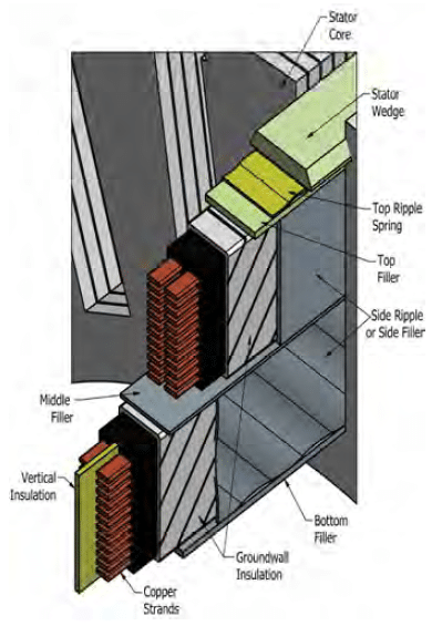
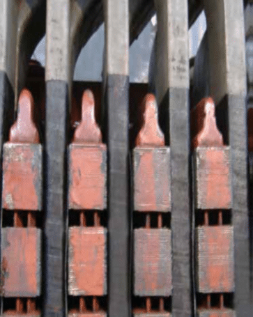
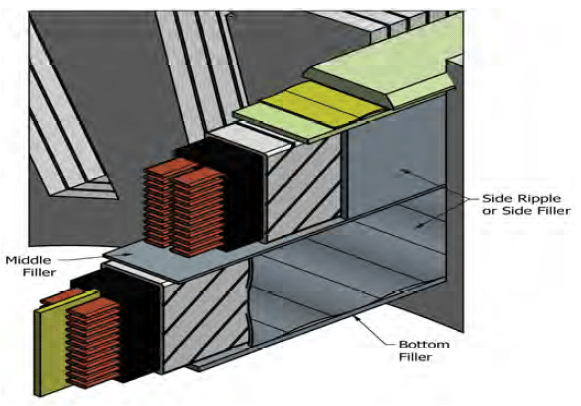
Semi-conductive bottom, middle, and side fillers are used to fill this space and tightly secure the slot’s stator bar, reducing the possibility of vibration erosion of the groundwall insulation. Semi-conductive side ripple springs are also used to secure the stator bar tightly against the slot laminations. If the slot contents shrink over time, a ripple spring will compensate, keeping the bar tight in the slot side to side. Ripple spring will also compensate for uneven space between the stator bar and stator core laminations.
The conductivity of these materials is important such that charge is dissipated efficiently, but conduction between laminations is not created. When installed properly, these semi-conductive materials provide a path to the ground (stator core) and dissipate excessive charge buildup without damaging the ground-wall insulation and stator core.
Surface Discharge:
Surface discharge can occur both in the stator slot and where the stator bar exits the stator core. Factors contributing to surface discharge include Moisture/humidity, dirt/contamination, and high electric field strength fluctuations at the end of the stator slots. Hydrogen-cooled generators running with reduced hydrogen pressure may experience an increase in partial discharge throughout the machine.
A semi-conductive coating on stator bars (on the slot portion) joined with a stress grading layer (silicon carbide) after the stator bar exits the stator slot can prevent surface discharge from occurring in these areas. The resistivity of the stress grading layer decreases as the electric field increases. This relationship is non-linear.
Semi-Conductive Material Properties
Whether using a coating, a flexible, or a rigid semi-conductive material, each plays a key role in preventing damage to stator bar ground-wall insulation and core iron due to corona/partial discharge in large rotating machines. Key properties critical to rigid semi-conductive materials protecting over time are:
» Surface Resistivity
» Thermal Class
» Compressive Strength
» Impact Resistance
Semi-conductive materials are used to prevent slot and surface partial discharge. Locations of these components are shown in the figure to the right.
Surface Resistivity:
It is most important that these semi-conductive materials have consistent and uniform surface resistivity between 500 and 50,000 Ohm/sq. (ideally 1,000 to 10,000 Ohm/sq.)
Surface resistivity lot-to-lot consistency can be verified through QA testing. It is equally critical that a semiconductive material can exhibit consistent surface resistivity performance across multiple lots to ensure the reliability of the partial discharge protection each time the material is used in the rotating machine.
| Resistivity using ASTM D 257 pressure electrode method | ||
|---|---|---|
| Target | C109 QA Data | |
| # of Tested Lots | — | 56 |
| Average, Ohms/Sq | 1,000 – 10,000 | 4,128 |
| Minimum | 500 | 900 |
| Maximum | 50,000 | 20,500 |
Thermal Rating:
Thermal rating is most important for maintaining mechanical properties and surface resistivity long-term through thermal cycling and upset conditions.
Thermal endurance test data comparing different materials is shown below. A product that can maintain stable surface resistivity at elevated temperatures will ensure optimal partial discharge protection, even in demanding temperature conditions.
| Target Resistivity using ASTM D 257 pressure electrode method* | ||||
|---|---|---|---|---|
| Hours | C109 | GGBE | G-11SC | GPSC |
| 0 | 2,330 | 7,670 | 1,870,000,000 | 35,000 |
| 72 | 2,230 | 2,270 | 9,672,000 | 16,000 |
| 192 | 2,800 | 1,260 | 1,600,000 | 9,330 |
| 240 | 2,930 | 1,230 | 1,600,000 | 9,670 |
| 360 | 2,170 | 1,000 | 733,330 | 7,670 |
| 720 | 2,400 | 970 | 433,330 | 8,670 |
| 1,440 | 3,260 | 700 | 433,330 | 11,330 |
| Average | 2,589 | 2,157 | 269,210,284 | 13,953 |
| Std, Dev. | 412 | 2,481 | Std, Dev. | 9,671 |
| Std, Dev. | 412 | 2,481 | Std, Dev. | 9,671 |
| Cv | 16% | 115% | 262% | 69% |
*Units are in Ohms/square
Compressive Strength
These rigid semi-conductive insulating components are exposed to compressive forces during the installation of the stator bars, during the wedging process, and throughout the insulation system’s life. Semi-conductive materials with higher compressive strength provide dimensional stability over time, ensuring the bars remain tight in the slot and that the gaps they fill, to prevent partial discharge, remain the same as when initially installed.
Impact Resistance
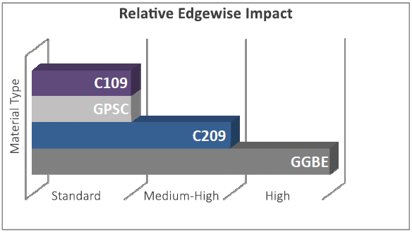
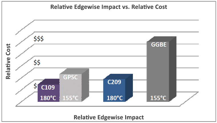
Bottom, middle, and side fillers are subject to impact forces during installation. Impact strength is critical to prevent/reduce damage during installation and repairs. Flat side fillers are exposed to edge driving forces during installation until the bar is tight in the slot. The chart below shows the relative edgewise impact force of various materials.
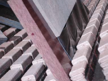
The Gund Company stocks several options of semi-conductive materials. The table below summarizes available materials, properties, and application location(s).
| Product Grade | C109 | C209 | GPSC | GGBE |
| Standard thicknesses, in (mm) | .020″ – .375″ (.5 – 9.5) | .008″ – .375″ (.2 – 9.5) | .015″ – .250″ (.2 – 1.0) | .008″ – .039″ (.2 – 1.0) |
| Construction | Semi-Conductive Glass Polyester | Semi-Conductive Glass Epoxy | Semi-Conductive Glass Phenolic | Semi-Conductive Glass Epoxy |
| Application Location | Bottom, Middle Filler | Side, Bottom, Middle Filler | Side, Bottom, Middle Filler | Side, Bottom, Middle Filler |
| Thermal Class | Class H – 180 °C | Class H – 180 °C | Class F – 155 °C | Class F – 155 °C |
| Surface Resistivity, Ohm/Sq | 500-50,000 | 500-50,000 | 200-20,000 | 500-30,000 |
| Compressive Strength, psi (MPa) | 49,000 (338) | 58,000 (400) | 48,000 (331) | 43,500 (300) |
| Izod Impact Strength, LW, ft-lbs/in | 12 | 13 | 11.8 | 9.2 |
| Flexural Strength psi (MPa) | ||||
|---|---|---|---|---|
| Lengthwise | 30,000 (207) | 57,000 (393) | 34,000 (234) | 43,500 (300) |
| Crosswise | 30,000 (228) | 80,000 (552) | 25,000 (172) | 43,500 (300) |
Summary
Stator insulation systems for rotating machines consist of a mixture of different materials, each performing a different function. These materials play a key role in preventing damage to stator bar ground-wall insulation during normal operation, upset conditions, and idle states. It is important to select stator insulating and semi-conductive components carefully. Dimensional stability and surface resistivity over time is critical and can determine the life of the insulating components. Proper installation of these components is equally important to ensure each component’s function is effective in its role.
References
» Handbook of Large Turbo-Generator Operation And Maintenance, Second Edition, Klempner-Kerzenbaum
» Rotating Electrical Machines & Power Systems, Second Edition, Patric-Fardo
» Electrical Insulation For Rotating Machines, Stone-Boulter-Culbert-Dhirani
» High Voltage Insulation Failure Mechanisms, IEEE International Symposium on Electrical Insulation, Vancouver, BC, 2008
» Corona Protection in Rotating High Voltage Machines, INDUCTICA 2006 Conference, Berlin
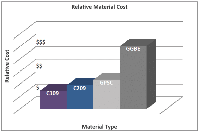
Material properties are important. Several options are available that allow cost to be included as a factor when selecting semi-conductive laminates.
When important properties such as surface resistivity and compressive strength are similar, deciding factors can be thermal class, cost, edgewise impact, and availability.
