Dielectric Strength -
A Key Test for Insulation Materials
Dielectric Strength is a critical property for any material with a primary function as an electrical insulator. In simple terms, dielectric strength is the ability of an insulating material to withstand applied electrical stress. It is defined as “the maximum electric field strength that a material can withstand intrinsically without breaking down; i.e., without experiencing failure of its insulating properties.”
When determining a material’s characteristics, it is important to consider the failure mode. A failure through the insulation thickness is called a puncture failure. If the insulation thickness is sufficiently great, failure can occur across the surface of the insulation. This is called creepage failure.
At the breakdown, the electric field frees bound electrons. Suppose the applied electric field is sufficiently high. In that case, free electrons may become accelerated to velocities that can liberate additional electrons during collisions with neutral atoms or molecules in a process called avalanche breakdown. Breakdown occurs abruptly (typically in nanoseconds), resulting in an electrically conductive path and a disruptive discharge through the material. A breakdown event severely degrades or even destroys solid materials’ insulating capability.
The field strength at which breakdown occurs in a given case depends on the respective geometrics of the dielectric (insulator) and the electrodes or conductor with which the electric field is applied and the rate of increase at which the electric field is applied. Because dielectric materials usually contain minute defects, the practical dielectric strength will be a fraction of the intrinsic dielectric strength seen for ideal, defect-free material. Thus, manufacturing quality has an essential impact on material performance. Since dielectric breakdown occurs as the acceleration of electrons within the insulating medium increases, the thermal loading of the insulation must also be considered. The heating of materials results in increased molecular motion. This tends to couple with the electrical stress, thus reducing the dielectric strength as temperature increases.
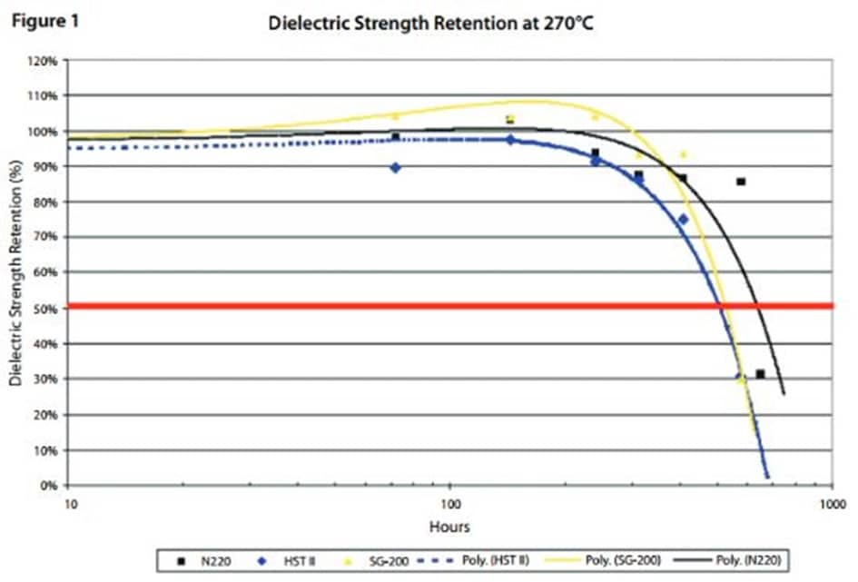
Note that the graph (see Figure 1) illustrates the change in the dielectric strength of three glass polyester laminate materials during a thermal aging study. Each material is a 220°C rated, high-temperature glass polyester laminate commonly used in dry-type transformer applications for components such as winding combs. After 300 hours of aging at 270°C, the dielectric strength remains unchanged. However, once the matrix breaks down thermally around 700 hours, the dielectric strength drops dramatically. The Gund Company’s complete material testing lab can perform side-by-side testing to compare materials’ performance, allowing companies to evaluate and approve material options.
The ASTM standard test method for dielectric breakdown voltage and dielectric strength of solid electrical insulating materials at commercial power frequencies is D-149. This test method is similar to IEC Publication243-1, with differences between D-149 and IEC 243-1 being mostly editorial. This test method is most commonly used to determine the dielectric breakdown voltage through the thickness of a test specimen. Most commonly, the test voltage is applied using simple test electrodes on opposite faces of specimens.
There are three test methods for voltage application:
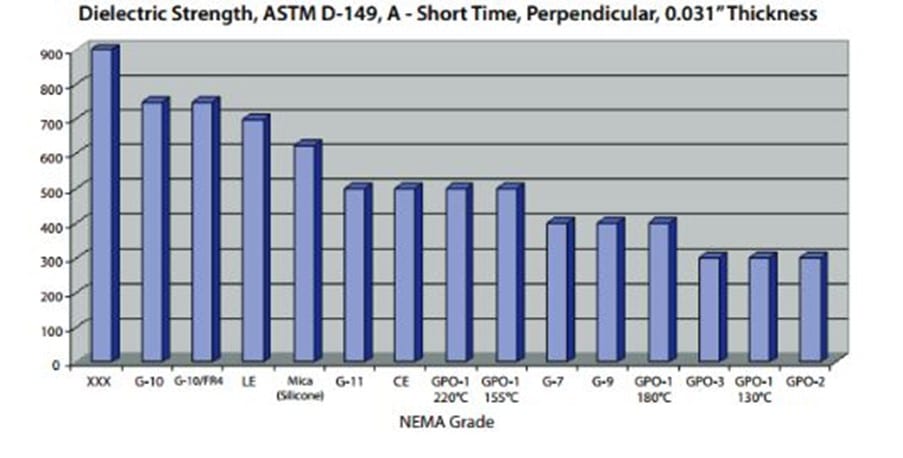
I. Method A, Short-Time Test – Apply voltage uniformly to the test electrodes from zero to one at a specific rate until breakdown occurs. Test results are expressed in volts per mil (1 mil = 0.001”) of the thickness of the tested material. It should be noted that relative dielectric strength decreases and material thickness increases, so a material at 0.031” in thickness will have a higher dielectric strength expressed in VPM (volts per mil) than a material tested at 0.250” thickness. NEMA Standards reflect this reality, as you can see from the chart below (figure 2) taken from the NEMA G-10 standard:
| Electrical Strength – Perpendicular to Laminations, V/mil. – short time | |
| 0.031” Thickness | 750 V/mil |
| 0.062” Thickness | 700 V/mil |
| 0.125” Thickness | 550 V/mil |
Figure 2
II. Method B, Step-by-Step Test – Apply voltage to the test electrodes at the preferred starting voltage and in specific steps and duration until breakdown occurs. Test results are expressed in total voltage (usually kV)required to cause a breakdown, so the thickness tested is critical. This method is primarily used with parallel pin electrodes.
III. Method C, Slow Rate-of-Rise Test – Apply voltage to the test electrodes from the starting voltage and at a specific rate until breakdown occurs. Method A is most commonly used for quality control tests, while Method B is commonly used when different materials are compared. Method B and C results are comparable to each other. Most material, technical datasheets will indicate the test method and the test condition per the standard. For example, the table below shows the material, and technical datasheet values for The Gund Company’s NEMA Grade GPO-3 material:
| Key Characteristics | Test Method | Units – English (SI) | NEMA Standard | Typical Values |
| Dielectric Strength Perpendicular in Oil (.0625”) | ASTM D-149(A-short) | V/mil (kV/mm) | 300 (11.8) | 550 (21.7) |
| Breakdown VoltageParallel Pin in Oil (.0625”) | ASTM D-149(Stepped) | kv | 40 | 50 |
figure 3
The test method indicates that ASTM D-149 was used for dielectric strength testing using Method, Short-Time Test. The test condition indicates that the electrodes were perpendicular to the thickness of the 1/16” thick material, and the test was done in dielectric oil. The NEMA Standard for GPO-3 requires a 300 volts per mil value, and The Gund Company material tested at 550 volts per mil on average for the lot testing. For the breakdown voltage test, ASTM D-149 followed Method B, Step-by-Step. Parallel pin electrodes were used in oil. The NEMA Standard for GPO-3 requires a 40 kV value, and the TGC material tested at 50 kV.
The table below (figure 4) includes a comparison of dielectric strength values per the NEMA Standard Authorization Engineering Information for several common grades of rigid insulation material:
Of course, these NEMA Standard values for dielectric strength are minimum values to meet that standard. Most manufacturers far exceed the minimum standard, as the table shows dielectric strength properties for NEMA GPO-3 (Figure 3).
If you have any questions about rigid insulation materials’ dielectric strength or dielectric breakdown voltage, we would be happy to review the topic in great detail. In addition, The Gund Company offers materials engineering presentations and training seminars for our customers to help them understand a wide range of modern material properties and capabilities. Suppose your company would like to compare the dielectric properties of two or more materials under consideration for a particular application design. In that case, our complete testing lab can offer some insight into material performance for your review.
Contact us today to learn more about the dielectric strength of specific materials or discuss your materials testing requirements.