Meets MIL-I-24768/2 Type GEE & ASTM D 709 01 TY IV Grade G-10
G-10 is a glass fabric-based laminate falls that under the Glass Cloth Epoxy category and is known for its low moisture absorption, even in high moisture environments, its abrasive texture, and its excellent electrical insulating properties.
NEMA grade G-10 glass epoxy is natural in color and non-brominated, meaning that unlike its FR4 counterpart, it is not flame retardant. All of our G-10 plastic is AS 9100D certified with ISO 9001:2018.
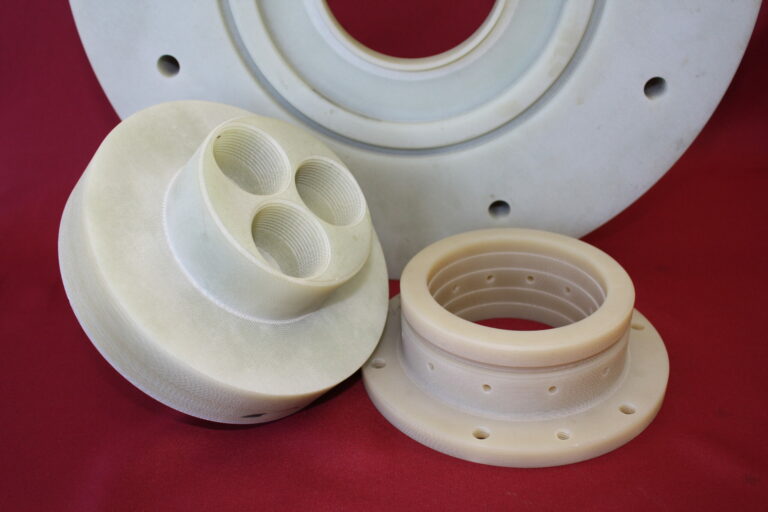
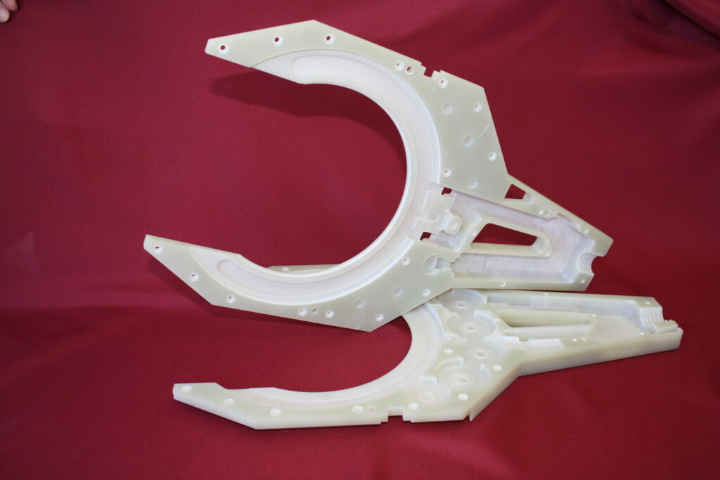
G-10 plastic machining is in an area in which The Gund Company excels, and we are capable of machining complex shapes.
G-10 MACHINED PARTS
KEY PROPERTIES:
Excellent electrical characteristics
Superior physical properties
Machinability
Immune to shrinkage
Almost impervious to water absorption
PROVEN APPLICATIONS FOR G-10 MACHINED PARTS:
Electrical – G-10 machined parts are ideal for electronic equipment because it remains stable at temperatures as high as 285 degrees Fahrenheit, and can be used as a heat or electrical insulator
Aerospace – The aerospace industry often uses G-10 machined parts to protect the electrical equipment used to operate the aircraft, protecting both the equipment and the operators